How to choose the right fiber optic cable type?
In high performance networking environments, such as 5G infrastructure, hyperscale data centers, and industrial IoT systems. Fiber optic cables serve as the backbone for ultra low latency, high capacity data transmission. With a wide variety of cable types, connectors, and performance specifications available, selecting the optimal solution for your deployment can be complex. This guide examines the key fiber optic cable categories, their unique advantages, and critical selection criteria, including bandwidth, distance, bend resistance, and environmental durability to help you make an informed decision for your specific application.
What Is a Fiber Optic Cable?
A fiber optic cable is a high-performance communication medium that transmits data as light signals through ultra-thin glass or plastic fibers. Designed for speed and reliability, it delivers exceptional bandwidth, minimal latency, and immunity to electromagnetic interference (EMI), outperforming traditional copper cabling. Fiber optic cables form the foundation of next-generation networks, enabling seamless connectivity in applications ranging from global internet backbones and 5G infrastructure to high-speed data centers and smart city systems, with support for data rates scaling from 10 Gbps to multi-terabit capacities.
Fiber Optic Patch Cable Types and How to Select the Best Option.
Fiber optic patch cables are available in multiple configurations, each designed to meet specific performance, distance, and environmental demands. To simplify your selection process, this guide organizes them into standard patch cable types and specialized high-performance variants—covering key differences in fiber mode, connector style, and construction. Whether you’re upgrading a data center, deploying a telecom network, or setting up an enterprise LAN, understanding these distinctions ensures optimal compatibility, speed, and reliability for your infrastructure.
Fiber optic patch cables serve as critical components in modern networking infrastructures, enabling seamless connectivity between active equipment such as optical transceivers, routers, and distribution frames. Designed for plug-and-play deployment, these cables feature factory-terminated connectors on both ends to guarantee consistent signal integrity and low insertion loss.
Patch cables can be systematically categorized according to several technical specifications, including: Transmission mode (single-mode vs. multi-mode), Fiber strand configuration (simplex, duplex, or multi-fiber), Jacket material (riser-rated, plenum-rated, or armored), Connector interface (LC, SC, MPO, etc.), Ferrule polish type (UPC, APC)
A thorough understanding of these parameters ensures optimal selection for your specific application—whether it’s short-reach data center interconnects, long-haul telecommunications links, or harsh industrial environments demanding ruggedized solutions.
By Fiber Mode: Single Mode vs. Multimode Fiber
Single mode fiber (SMF) and multimode fiber (MMF) represent the two fundamental classifications of optical fiber cables, distinguished by their core diameter, light propagation characteristics, and deployment use cases:
Single Mode Fiber (SMF)
Core Size: Ultra-thin 8-10μm core diameter that permits only a single light mode propagation.
Performance Advantages: Enables virtually unlimited bandwidth with near-zero chromatic dispersion, supporting transmission distances exceeding 80km without amplification
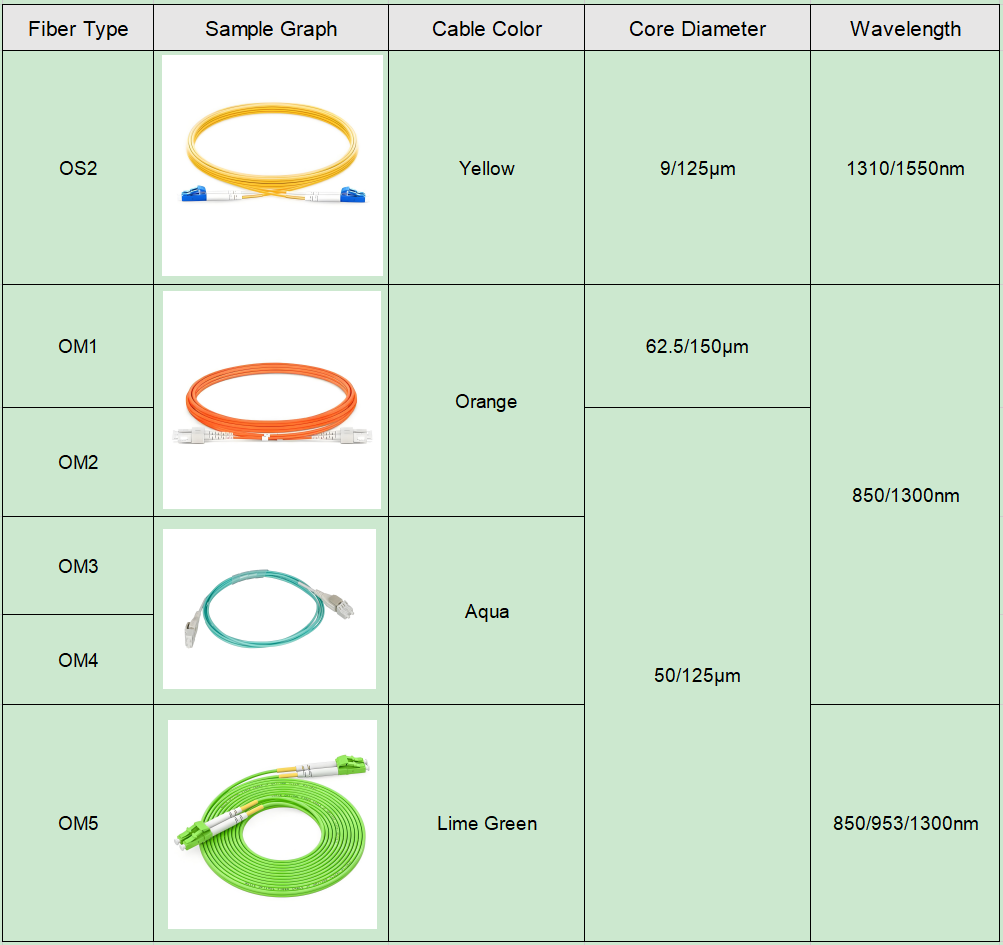
Industry Standards:
• OS2: The current benchmark for long-haul applications, featuring improved attenuation specifications (<0.4dB/km) and enhanced bending performance
• OS1: Legacy specification with higher attenuation (1dB/km), now primarily found in legacy installations
Primary Applications: Carrier-grade networks, FTTH backbones, and high-speed financial trading links.
Multimode Fiber (MMF)
Core Dimensions: Significantly larger 50μm or 62.5μm core that facilitates multiple light modes
Generational Evolution:
• OM4/OM5: Modern laser-optimized fibers supporting 400G Ethernet up to 150m using parallel optics
• OM3: Cost-effective solution for 10G-40G deployments within data centers
• OM1/OM2: Obsolete technologies limited to 1Gbps applications
Optimal Use Cases: Data center inter-rack connectivity, enterprise building backbones, and industrial automation systems.
By Fiber Count: Simplex vs. Duplex Fiber Cables
Fiber optic patch cables are primarily differentiated by fiber strand configuration, with simplex and duplex being the two fundamental types:
Simplex Fiber Cables
Construction: Single optical fiber strand in a protective jacket
Transmission Method:
• Unidirectional data flow (single-channel)
• Bidirectional capability when paired with BiDi transceivers (using wavelength division multiplexing)
Key Applications:
• Monitoring systems (e.g., CCTV fiber links)
• Industrial sensor networks
• Space-constrained installations where minimal cabling is critical
Duplex Fiber Cables
Construction: Two parallel fibers (typically color-coded as Tx/Rx) in a single jacket
Transmission Method:
• True full-duplex communication with dedicated send/receive paths
• Standard implementation for transceiver pairs (SFP+, QSFP, etc.)
Key Applications:
• Enterprise network switches and routers
• Data center interconnects
• Any application requiring simultaneous bidirectional traffic
Selection Guidelines:
Choose Simplex when:
Using BiDi optics (saves fiber infrastructure).
Deploying unidirectional systems.
Working with tight bend radius requirements.
Choose Duplex when:
Implementing standard transceiver configurations.
Future-proofing for potential speed upgrades.
Needing separate physical paths for transmit/receive signals.
By Cable Jacket: Riser (OFNR) vs. LSZH vs. Plenum (OFNP) Fiber Cables
Fiber optic cable jackets are engineered for specific installation environments and fire safety requirements, with three primary classifications:
OFNR (Riser-rated) Cables
Fire Rating: Meets UL 1666 flame propagation test for vertical riser applications.
Key Characteristics:
• Cost-effective PVC-based jacket material.
• Releases toxic halogen gases when combusted.
Typical Applications:
• Inter-floor vertical runs in building riser shafts.
• Non-plenum areas without air circulation.
LSZH (Low Smoke Zero Halogen) Cables
Fire Rating: Complies with IEC 60754-1/2 and IEC 61034 smoke emission standards.
Key Advantages:
• Produces minimal smoke and no corrosive halogen acids.
• 80% less toxic gas emission compared to PVC.
Mandatory Installations:
• Public transportation systems (subways, airports).
• Healthcare facilities and educational institutions.
• Any confined space with limited ventilation.
OFNP (Plenum-rated) Cables
Fire Rating: Exceeds UL 910 Steiner Tunnel test for plenum spaces.
Critical Features:
• Fluoropolymer jacket with self-extinguishing properties.
• Lowest flame spread rating (<1.5m).
Required Use Cases:
• Above-ceiling spaces with air circulation.
• HVAC ducts and environmental air handling areas.
Selection Guidelines:
Prioritize OFNP for:
Any space used for air return/ventilation (per NEC 300.22).
High-rise buildings with centralized air systems.
Specify LSZH when:
Human safety is paramount (evacuation routes).
Installing in metal conduit doesn’t eliminate toxicity concerns.
Use OFNR only for:
Dedicated riser shafts with firestops.
Cost-sensitive projects where code permits.
By Connector Type: LC, SC, ST, MTRJ & Other Fiber Optic Interfaces
Fiber optic connectors are critical components that determine installation density, performance reliability, and maintenance efficiency in optical networks. The industry offers multiple standardized connector types, each optimized for specific deployment scenarios:
LC (Lucent Connector)
Key Features:
• 1.25mm ferrule (50% smaller than SC).
• Push-pull latching mechanism.
• Dual LC configurations for duplex applications.
Primary Use: High-density patching in data centers and enterprise switches.
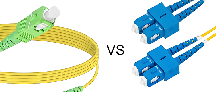
SC (Subscriber Connector)
Key Features:
• 2.5mm ferrule with snap-in coupling.
• Excellent insertion loss stability (<0.3dB).
Dominant Applications:
• FTTH drop cables.
• Telecom backbone connections.
ST (Straight Tip)
Key Features:
• Bayonet-style locking mechanism.
• 2.5mm keyed ferrule.
Legacy Usage:
• Campus network backbones.
• Industrial environments requiring vibration resistance.
MTRJ (Mechanical Transfer Registered Jack)
Key Features:
• Dual-fiber plastic housing.
• RJ-45 style latch.
Niche Applications:
• Space-constrained enterprise networks.
• Pre-2010 network equipment interfaces.
Emerging Connector Technologies.
CS (32-fiber array for 400G/800G).
SN (Multi-fiber push-on for 5G fronthaul).
MDC (Ultra-high density with 1.25mm pitch).
Selection Criteria:
Choose LC for modern high-density installations.
Specify SC for telecom-grade reliability.
Consider MPO/MTP for parallel optic systems.
Reserve ST for legacy system maintenance.
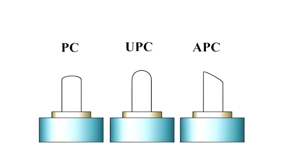
By Polishing Type: PC vs. UPC vs. APC Connectors
The end-face polish of fiber optic connectors critically determines optical performance, particularly in terms of insertion loss and return loss characteristics. These polishing standards directly impact signal integrity across different network applications:
UPC (Ultra Physical Contact)
Polish Geometry:
• Curved convex surface with ultra-precise finish.
• Typical return loss: -50dB to -55dB.
Performance Advantages:
• 30% lower insertion loss than basic PC polish.
• Excellent for high-frequency signal transmission.
Ideal Applications:
• Enterprise network equipment interconnects.
• Data center 10G-400G Ethernet links.
• Digital CATV distribution systems.
APC (Angled Physical Contact)
Polish Geometry:
• 8-degree angled end-face with fine grinding.
• Achieves return loss better than -60dB.
Critical Benefits:
• Virtually eliminates Fresnel reflections.
• Essential for analog signal integrity.
Required Use Cases:
• GPON/EPON fiber-to-the-home networks.
• RF video overlay systems.
• Coherent DWDM transmission systems.
PC (Physical Contact)
Historical Context:
• Flat polish with micro-sphere curvature.
• Limited to -40dB return loss performance.
Current Status:
• Phased out in modern deployments.
• Occasionally found in legacy CATV systems.
Selection Guidelines:
Mandate APC for:
Any analog optical transmission.
High-power laser systems (>10mW).
Long-reach single-mode applications.
Default to UPC for:
Standard digital communication links.
Multi-mode fiber installations.
Cost-sensitive projects without RF requirements.
Avoid PC in:
New installations.
High-speed coherent systems.
Reflection-sensitive applications.
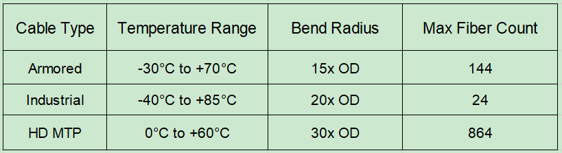
Specialty Fiber Optic Cable Solutions
Engineered for extreme environments and mission-critical applications, these advanced fiber cables deliver reliability where standard solutions fail:
Armored Fiber Cables
Protection System:
• Corrugated stainless steel tape armor.
• Anti-rodent Kevlar® reinforcement layer.
Survivability Features:
• Withstands 2000N crush resistance.
• 500kg tensile load capacity.
Deployment Scenarios:
• Oil/gas field monitoring networks.
• Military tactical fiber systems.
• Data center perimeter security links.
Industrial-Grade Fiber Cables
Harsh Environment Design:
• UL/CSA certified oil-resistant jacket.
• -40°C to +85°C operational range.
Mechanical Robustness:
• IP67-rated hermetic sealing.
• 10G vibration endurance (IEC 60068-2-6).
Typical Installations:
• Factory automation control loops.
• Wind turbine generator arrays.
• Railway signaling systems.
Ultra-High Density Cables
Space Optimization:
• 4-fiber MTP® to 8xLC breakout design.
• 60% reduction in tray fill ratio.
Data Center Advantages:
• 1U cable management for 144 fibers.
• Tool-less reconfiguration capability.
Next-Gen Ready:
• Pre-terminated 400G SR8 compatibility.
• OM5 wideband multimode support.
5G FTTA Solutions
Antenna Site Features:
• UV-stabilized PE outer jacket.
• Pressurized gel-filled core design.
• Phase-stable polarization maintaining variants.
Radio Unit Connectivity:
• AAU to DU fiber midhaul (ECPRI).
• mmWave small cell fronthaul.
Polarization Maintaining (PM) Fiber
Precision Light Control:
• <0.1dB polarization crosstalk.
• 0.1° angular alignment ferrules.
Quantum-Ready Applications:
• Fiber optic gyroscopes.
• Coherent LiDAR systems.
• QKD network backbones.
Selection Matrix:
Note: All specialty cables require customized inspection procedures – PM fibers demand particular attention to connector key alignment.
Conclusion
Selecting the optimal fiber optic cable solution is critical for ensuring peak network performance, minimizing signal degradation, and maintaining long-term system scalability. By carefully evaluating key parameters—including fiber mode, connector type, jacket rating, and application-specific requirements—you can implement a robust optical infrastructure that delivers reliable transmission while meeting both current demands and future bandwidth growth. Whether deploying in data centers, industrial settings, or telecom networks, the right fiber choice bridges the gap between theoretical performance and real-world operational excellence.
Final Recommendation: Always conduct end-to-end link loss budget calculations and verify compatibility with existing infrastructure before finalizing your fiber selection.